View-angle tilting MRI (part 3): Fewer approximations
This is a third (and presumably final) text about view-angle tilting (or VAT) MRI concluding the explanations posted on 2020-09-10 and on 2020-09-15. I don’t really like the mathematical approximations that I used in my first text and, therefore, I would like to try again; the simple graphical visualization should correspond to an equally simple mathematical derivation …
Let’s start as before with the MRI signal equation for an excited slice without any distortions
with frequency-encoding direction x and frequency-encoding gradient Gx (phase encoding is generously omitted). The x integral is over the complete imaged object (but for a compact object that fits into our field of view, we can integrate from – ∞ to ∞). The slice-selection direction is denoted by ẑ, where I use the hatted (“^”) variable to differentiate the undistorted (original) slice position ẑ from the distorted position z = z(x) analyzed below.
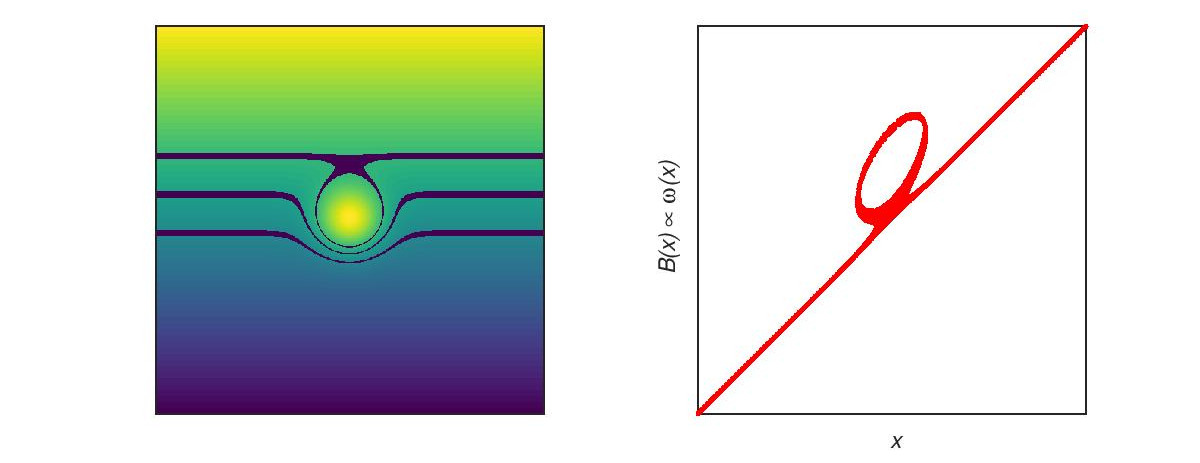
I will ignore the slice thickness, since the essence of the VAT technique can pretty well be explained without it. And everything gets really complicated if we consider varying slice thicknesses – or even slices split in several parts as illustrated in the following figure.

It’s useful to keep in mind the resonance relation between an excitation pulse with frequency ωrf applied after switching on the slice-selection gradient Gz,slc and the slice position ẑ (without field inhomogeneities):
If we now consider inhomogeneity-induced distortions of a slice (due to a field inhomogeneity, ΔB(x,z)), then each original slice position ẑ (corresponding to the excitation frequency ωrf) is “moved” to a new position, z(x), which is, in general, different for each x. The new position, z(x), is the solution of the equation
for each (fixed) value of x. The relation to the original slice position, ẑ, can be expressed (after division by γGz,slc) as
which can be re-arranged to
(Of course, the previous equation is not an explicit solution describing z(x), since z(x) still appears also on the right-hand side of the equation.)
If we go back to the MRI signal equation and include the distorted slice geometry, z(x), the integral changes to
where, ω(x,z) is used to describe the Larmor frequencies during readout. Without field inhomogeneities, this is simply (and independent of z) ω(x,z) = γGx x. The inhomogeneity, ΔB(x,z) changes the Larmor frequencies to ω(x,z(x)) = γ (Gx x + ΔB(x, z(x))). If we also include the additional VAT readout gradient, Gz,VAT, we get
We can now insert the expression for z(x) derived above into the third addend of this last expression, which gives
So, by setting Gz,VAT = Gz,slc (as proposed for VAT MRI), the inner parenthesis vanishes and neither ΔB nor z(x) (which implicitly contains ΔB as well) appears in the expression for the Larmor frequency. This means that the artifacts in readout direction (due to changed readout frequencies) are removed:
Other artifacts caused by the changed slice geometry, z(x), obviously remain (as indicated by the term ρ(x, z(x)) in the integral) and are not corrected by the VAT approach.
Since I’ve omitted the integration (∫dz …) over the finite slice thickness, the meaning of the slice coordinate ẑ in the final results is not completely obvious. Actually, the appearance of ẑ during readout corresponds to a tilted readout (that’s why it’s called view-angle tilting), which becomes clearer if one includes the omitted integration over the slice direction in the resulting MRI signal equation.
pdf version available
URL: <https://dtrx.de/od/mmm/mmm_20200929.html>